
|

|
|
|
|
|
This page of the JHDL user's manual describes how to use JHDL to develop complete, deployable applications. That is, the features of JHDL and CVT are extended and customized to create a final application that is useful to the end user. The final product should be usable even if the user does not know how to use JHDL or create digital logic designs.
This page includes a section on the philosophies behind the approach for application development presented on this page. Next, details of the CVT architecture are presented. Then, a detailed description for the development of an example application is given.
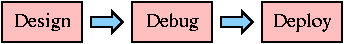
Developing complete JHDL-based applications generally occurs in three phases. These are 1) design, 2) debug, and 3) deploy. The design phase encompasses such tasks as specification development, implementation decisions, implementation, and other related tasks. The debug phase is when the results of the design phase are verified. The deploy stage is when the final application is packaged into a format that is usable by the end user. Once the deployment is complete, the end user may run the application without the need of special skills in digital logic design or JHDL. Nevertheless, the power of JHDL and the flexibility of the configurable computing hardware on which the application runs may still be present and accessible by the end user if the deploy phase is done accordingly. Often the design and debug phases are repeated in an iterative fashion until the design is complete and verified. When building a design using the bottom-up style, iterations of the design and debug phases often build on top of previous iterations. The example of the of an application given on this page uses this a approach to build up an application in four stages.
|
| Figure 1. The development process proceeds through the three phases of design, debug, and deploy |
All applications for configurable computing have data input and data output. Inputted data is manipulated by the application to produce the desired results which are sent to the data output. This process is structured and orchestrated by the application control.
Based on these observations and the need to create an application architecture that is sound, modular, and extensible, software engineers created an architecture model known as Model-View-Controller. The model-view-controller architecture is the same architecture used in the various components of the Java Swing classes, as well as in many other major software applications. The different components of the model-view-controller architecture function as follows:
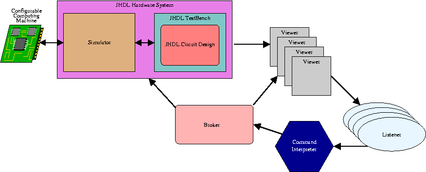
For a JHDL-based application, the model is the JHDL circuit itself. The JHDL model represents the circuit structure and state of the hardware design. For traditional circuit verification using JHDL, the view is the set of trees, tables, schematics, waveforms, and other viewers made available by the CVT suite of tools. For complete, deployed applications, the view is whatever data I/O and user I/O system that makes sense for the given application. The controller for a JHDL-based application is contained mostly in the class byucc.jhdl.apps.Broker. This class accepts input from the JHDL command line interpreter to perform such tasks as running the JHDL simulator/execution environment and opening new viewers.
The creation of a JHDL-based design focuses on extending the model, view, and controller components of the applications architecture. The following example application demonstrates how this may be done.
|
| Figure 2. The CVT architecture. |
This example application implements a customizable network monitor/filter. The application hardware bridges two halves of a network. Packets entering one end are passed through to the other end. At execution time, the application accepts two lists of network addresses from the user. The first list contains addresses that the hardware should track simply to maintain a count of hits to the given addresses. The second list tells the application to perform the same counting function, plus matching packet destination addresses should then not be allowed to pass through the system.
We will build up this application from the bottom up in four stages. The process listed here is not meant to document every minor detail of the development process. Rather it shows the development details relevant to using JHDL and CVT. This will give information on the relationships of the various components of CVT and how one might create other applications based on the CVT architecture.
The first stage of development will create a low-level component of the application. This component is simply a comparator coupled with an up-counter.
The model for stage one is a single JHDL design made up of an parameterizable Equals module and an up-counter. At circuit build time, a constant value is embedded into the Equals module. The output of the Equals module is a signal to tell the up-counter to increment.
The view for stage one is provided by the default CVT system. Additionally, a very basic bar graph viewer is used to monitor the output of the up-counter. This viewer merely displays a portion of the application state. It does not act as an interactive component to accept user input for the application. That role is played by the standard CVT system.
The controller for stage one is provided by the standard Broker system provided by CVT. This stage of development does not perform any customizations to the default CVT system. However, much of the functionality that a controller might perform to support the custom viewer (the bar graph) is performed in the TestBench for the design.
The application is not ready for final deployment in stage one. However, the developer still needs a way to combine the application components to perform the steps in the debug phase. This is done in a TestBench. The TestBench for this stage of development simply creates an instance of the design, inserts it into the CVT system, creates a custom bar graph viewer, and links the whole system together.
Although this isn't the final deployment step of the application development, it gives an indication of how the development may proceed with design and debug, while still keeping in mind the eventual need for application deployment. Preparations are made from the very beginning to eventually create the final product to be deployed to the end user. One of the features of the TestBench in this stage is that it reads in data from the user to set up the parameters that define the structure of the circuit design. This type flexibility and mutability in the final hardware configuration will remain in the application not only in the design and debug phases, but in the deploy phase and beyond as well.
To verify the application so far, simply download the following
Java files, compile them (with the required JHDL classes or Jar in
your classpath) and execute the main method of the
TestHitCounter class. If you don't give it any arguments it quits
after indicating the proper command line syntax. The following
command line will build a HitCounter circuit with a 5-bit input
and a 10-bit output. The value 3 will be embedded in its Equals
comparator.
java TestHitCounter 3 5 10
Once this is loaded up, you may use the "setinput"
script to set a sequence of values to put on the input wire. Just
execute source setinput on the CVT command line. As
you cycle through that sequence, you will notice the bar graph
value increments every time the input is 3.
From here, you may experiment further to verify the correctness of the circuit, including building it with varying parameters. Don't forget to excercise the functionality of the "restart" wire as well as the main input wire.
| HitCounter.java | A parameterizable JHDL design that comprises the application model in stage one |
| GraphCanvas.java | A simple bar graph viewer for use as a custom viewer for the application |
| TestHitCounter.java | The TestBench for the HitCounter design |
| setinput | A JHDL command line script that may be used for convenience in setting up a schedule of values to put on the input wire |
The second stage of development builds on the HitCounter design from stage one. This is another step in the progression toward completing the full application design according to the specifications.
The model for stage two is a JHDL design that creates an array of instances of the HitCounter design from stage one. The input for each HitCounter is the same bus wire, but the constant value embedded in each HitCounter may be different.
The view for stage two is the same as that of stage one. However, this time, the features of the GraphCanvas viewer are tested more fully by telling it to display the values of multiple counter outputs.
The controller for stage two is basically the same as that in stage one. Only this time, the TestBench is set up such that it is capable of dealing with multiple counter values.
Once again, the application is still not ready for final deployment. But, as in stage one, the TestBench acts as a central command point that will eventually become something like the final deployment point of the application.
To verify the application so far, simply download the following
Java files, compile them (with the required JHDL classes or Jar in
your classpath) and execute the main method of the
TestHitCounters class. If you don't give it any arguments it
quits after indicating the proper command line syntax. The
following command line will build an array of HitCounter circuits
with 5-bit inputs and 10-bit outputs. The values 3, 5, 6, 7, 1,
and 9 will be embedded in the various Equals comparators.
java TestHitCounters 5 10 3 5 6 7 1 9
Once this is loaded up, you may use the "setinput" script to set a sequence of values to put on the input wire. As you cycle through that sequence, you will notice the bar graph values increment for every HitCounter value that corresponds to the current input.
From here, you may experiment further to verify the correctness of the circuit, including building it with varying parameters. Don't forget to excercise the functionality of the "restart" wire as well as the main input wire.
| HitCounter.java | A parameterizable JHDL design that makes up part of the the application model in stage two |
| HitCounterArray.java | A parameterizable JHDL design made up of various HitCounter |
| GraphCanvas.java | A simple bar graph viewer for use as a custom viewer for the application |
| TestHitCounters.java | The TestBench for the HitCounter design |
| setinput | A JHDL command line script that may be used for convenience in setting up a schedule of values to put on the input wire |
The third stage of development finalizes the network monitor application design. This is the last stage in which we will use the full CVT system to help us debug the design.
The model for stage three is a JHDL design that creates two instances of the HitCounterArray from stage two. The first array is for the addresses to just count. The second array is the for the addresses to be blocked. When an address to be blocked is detected, it disables a register that normally allows the input packet to pass through the design.
The view for stage three is nearly the same as that of stage two. However, the bottom of the view now displays a label that helps in the debugging of the hits. Such custom variations to the application view help out the developer to test various points of particular interest as the design is being debugged.
The controller for stage three is basically the same as that in stage two. Slight modifications were required to accomodate the differences in the top-level part of the design.
Yet again, the application is still not ready for final deployment. But, as in stages one and two, the TestBench acts as a central command point that will eventually become something like the final deployment point of the application.
To verify the application so far, simply download the following
Java files, compile them (with the required JHDL classes or Jar in
your classpath) and execute the main method of the
TestMonitor class. If you don't give it any arguments it
quits after indicating the proper command line syntax. The
following command line will build two array of HitCounter circuits.
The first array will simply count hits to addresses 1, 3, and 5.
The second array will count hits to addresses 6, 8, and 9, and
packets to those addresses will also be filtered.
java TestMonitor 1 3 5 - 6 8 9
Once this is loaded up, you may use the "setpackets" script to set a sequence of values to put on the input wire. As you cycle through that sequence, you will notice the bar graph values increment for every HitCounter value that corresponds to the current input. You will also notice that hits to the to-block list of addresses will cause the packets to not be able to pass through the circuit.
From here, you may experiment further to verify the correctness of the circuit, including building it with varying parameters. Don't forget to excercise the functionality of the "restart" wire as well as the main input wire. The label on the bottom of the viewer should be helpful in single-stepping through the circuit simulation.
| HitCounter.java | A parameterizable JHDL design that makes up part of the the application model |
| HitCounterArray.java | A parameterizable JHDL design made up of various HitCounter |
| NetworkMonitor.java | The final network monitor/filter hardware configuration design |
| GraphCanvas.java | A simple bar graph viewer for use as a custom viewer for the application |
| TestMonitor.java | The TestBench for the NetworkMonitor design |
| setpackets | A JHDL command line script that may be used for convenience in setting up a schedule of values to put on the input wire |
This is the final stage in our application development. After stage three, we are confident that the hardware design is correct and that the custom viewer system is capable of performing well along with the hardware. Now we just need to finalize the combination of the application pieces. This is the point in which we establish the deployment-time features of the application.
The model for stage four is exactly the same as the parameterizable network monitor/filter from stage three.
The view for stage four uses the same GraphCanvas from the previous stages. However, now we want to present the view in the final format for the end user. The user won't care to use the default CVT system that we used before. That was mostly just for the benefit of the developer during debug. Now we want the interface to the application to be just what the user needs and no more. It should be simple and usable. The viewer we use here has a tabbed pane that contains a pane for the address hits to count and one for the addresses to count and block. The viewer also has a button. This button does not do anything until it is configured by an external entity.
In stage four, for the first time our controller is a more sophisticated system that extends and customizes the CVT architectural components. In this case, the controller is made up of a class that extends the Broker class. It is this class that creates and configures the application viewer. The main interactions with the viewer take place through a separate helper class. One of the configurations for the viewer is the setup for the customizable button. In this case the button generates a textual command that is processed by the CVT command line interpreter. The interpreter then performs the appropriate tasks called for in the custom Broker to simply reset the circuit counters.
Make sure you take a close look at the source code to the various classes. Look for the ways in which the classes relate to each other and how that corresponds to Figure 2 above. From this example application you should be able to learn good ways in which to build up your own complete applications based on JHDL and CVT.
Finally we are ready to deploy this applicatoin. The main execution point of the application again is a "TestBench" However, don't let the name fool you. Even though it is called a TestBench, it is merely an artifact of traditional naming schemes. The TestBench is simply a place holder for the hardware design as it resides in the JHDL hardware system. So the TestBench is not present to test the design, but to act as an interface for entities outside of the JHDL system. In the case of this application, the TestBench does no more than than build the circuit based on parameters provided by the user at execution time and an instance of a custom controller.
The custom controller is contained in the MonitorBroker class. This class creates the application viewer, creates a custom text-based command to corresponde with the viewer, and it also creates a helper class to interact with the viewer. All of the circuit interactions pass through this Broker. It is the central runtime execution manager for the application system.
To run the application, simply download the following
Java files, compile them (with the required JHDL classes or Jar in
your classpath) and execute the main method of the
Monitor class. If you don't give it any arguments it
quits after indicating the proper command line syntax. The
following command line will build two array of HitCounter circuits.
The first array will simply count hits to addresses 1, 3, and 5.
The second array will count hits to addresses 6, 8, and 9, and
packets to those addresses will also be filtered.
java Monitor 1 3 5 - 6 8 9
As is, this application only runs in simulation mode.
Once it is loaded up, you may use the "setpackets"
script to set a sequence of values to put on the input wire. Just
execute the command source setpackets on the command
line provided by the custom viewer. Other commands such as step
and cycle may also be used to run the application. As
you cycle through that sequence, you will notice the bar graph
values increment for every HitCounter value that corresponds to
the current input. You will also notice that hits to the to-block
list of addresses will cause the packets to not be able to pass
through the circuit.
From here, you may experiment further to verify the correctness of the circuit and the viewer, including building it with varying parameters. Don't forget to excercise the functionality of the "restart" wire, which may also be done by pressing the button on the viewer, as well as the main input wire.
| HitCounter.java | A parameterizable JHDL design that makes up part of the the application model |
| HitCounterArray.java | A parameterizable JHDL design made up of various HitCounter |
| NetworkMonitor.java | The final network monitor/filter hardware configuration design |
| GraphCanvas.java | A simple bar graph viewer for use as a custom viewer for the application |
| MonitorViewerPanel.java | The complete, custom viewer for the Monitor application |
| ButtonListener.java | Classes implement this interface to set up and listen to the MonitorViewerPanel's button |
| MonitorBroker.java | The custom extension of the Broker class to act as the controller |
| ViewIntermediary.java | Implements the ButtonListener interface to help the MonitorBroker and the MonitorViewerPanel work with each other |
| Monitor.java | The "TestBench" and execution point for the application |
| setpackets | A JHDL command line script that may be used for convenience in setting up a schedule of values to put on the input wire |
The example application presented above shows how to use JHDL and CVT to create a standalone application that simulates a hardware design as it acts as the processor for an application. However, the real end product should be something that executes in physical configurable computing machine hardware. That means that one more important step of the deploy phase of development is to link the design into a JHDL model for a specific platform. The debugging should then also include verification of the application in hardware mode.
The final, deployed application built up by this system maintains JHDL and CVT as integral parts included in it. That means that the final application retains the design reconfigurability and parameterizability made possible by the JHDL system. This is a tremendous benefit, especially since it enable optimizations based on user input at execution time, such as the constant-value equals comparators of the above example application.
However, such optimizations may still depend on the presence of other tools when the application is executed. For example, if the optimizations require major structural modifications to the hardware configuration, another place and route process may need to be performed. If the same basic design structure remains intact, other methods may be employed to insert the design optimizations. These may include scan chain configurations, bit stream modifications, or low-level hardware configuration modifications using tools such as JBits.
No matter what method the application uses to implement execution-time optimizations, the planning for them should be done from the very beginning of application development.
For more information on the development process using JHDL and CVT, as well the model-view-controller architecture and design, debug, deploy philosophy, see the following paper and thesis:
| | JHDL Home Page | Configurable Computing Lab | Prev (Tri-State) | Next (CLI) | |
![]()
JHDL 0.3.45
Copyright (c) 1998-2003 Brigham Young University. All rights reserved.
Last updated on 11 May 2006